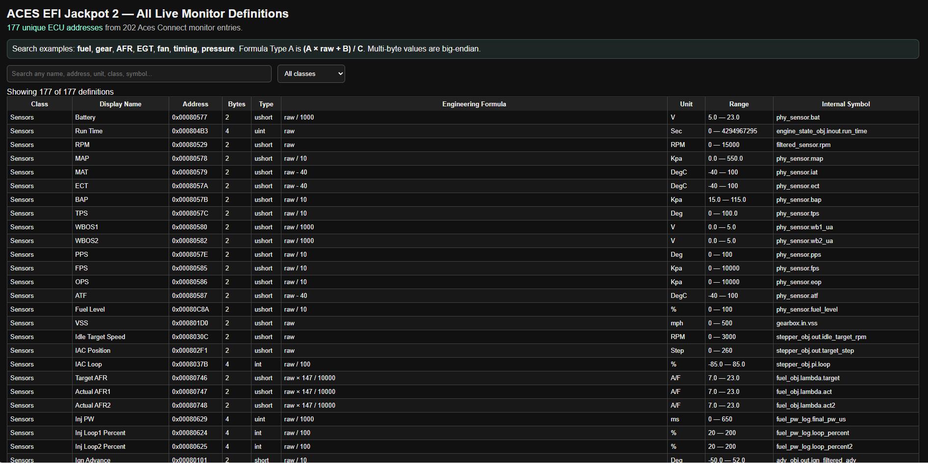
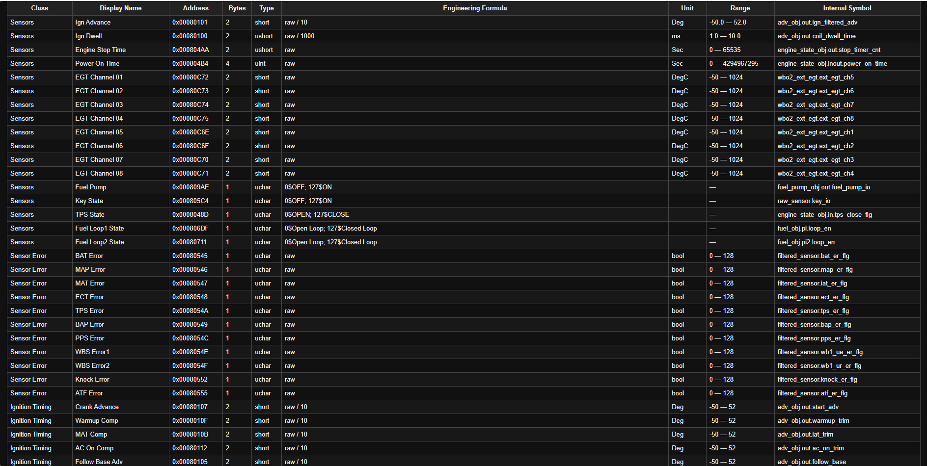
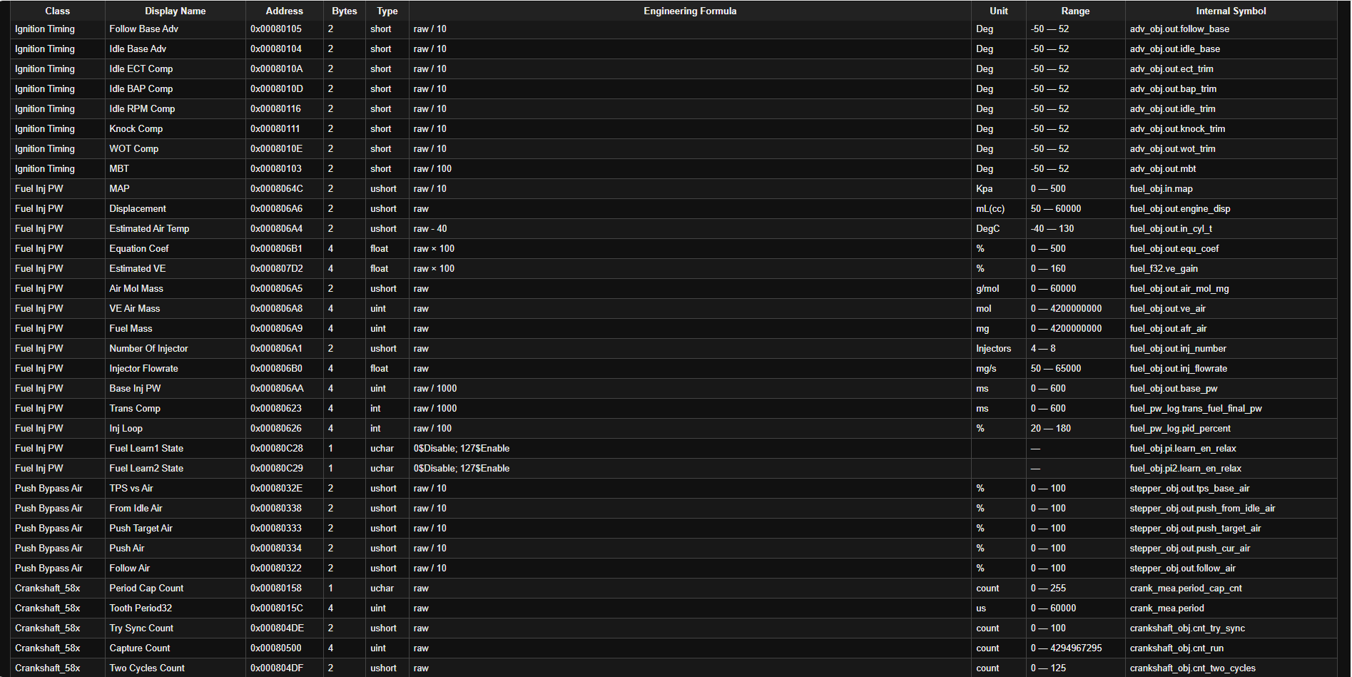
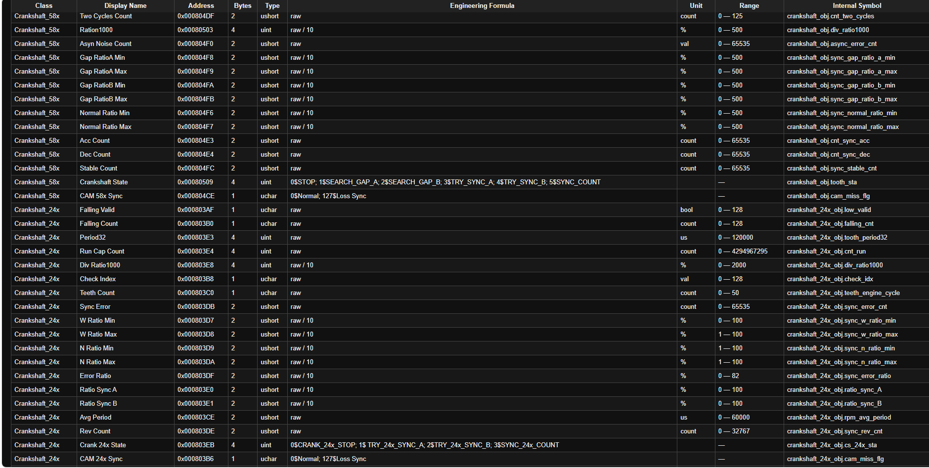
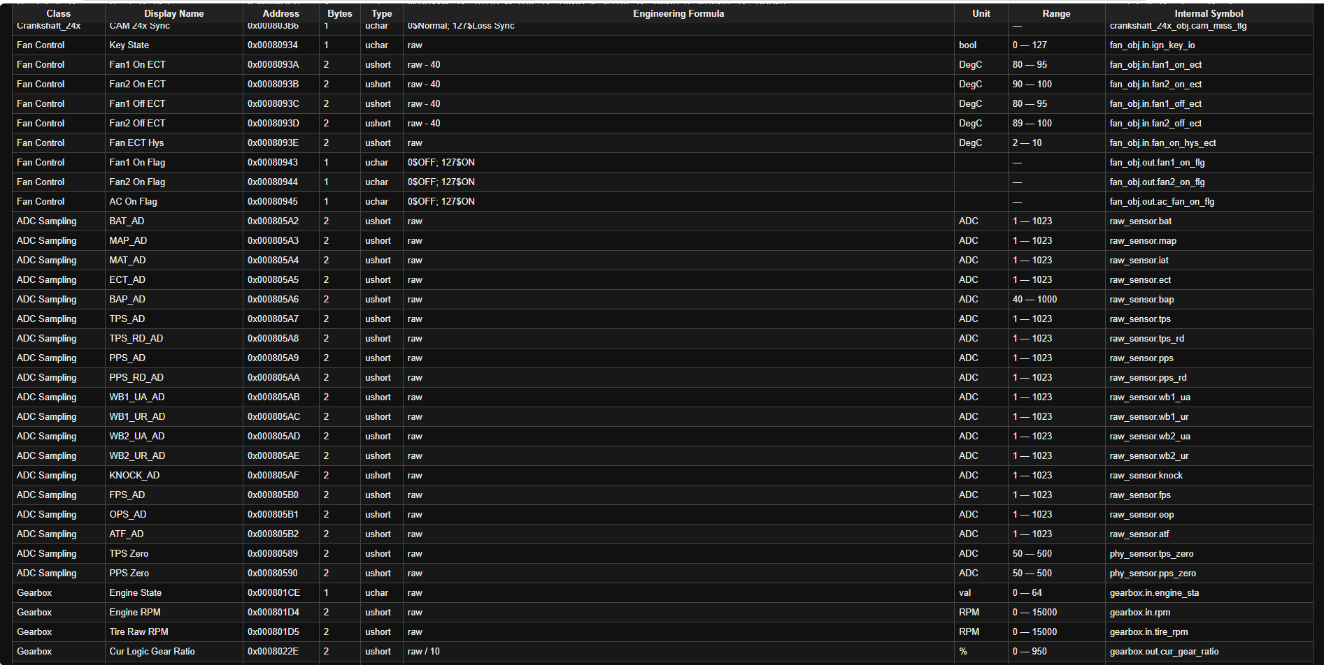
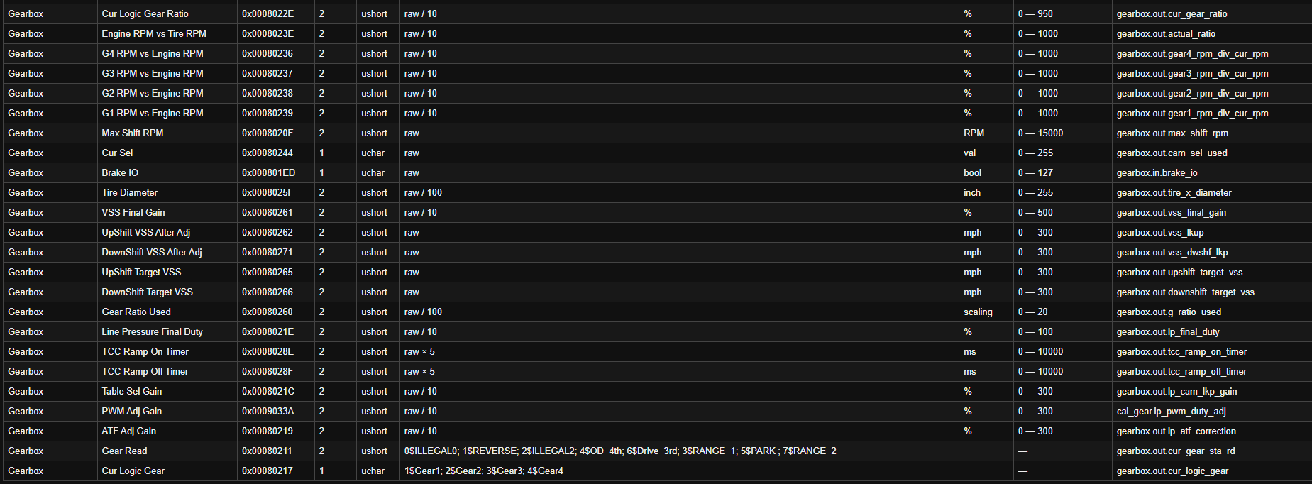
Could you provide source for this material for easier integration.
the material was derived from reverse engineerinf live CAN-bus traffic from an ACES EFI jackpot 2 system. it is not copied from an official ACES CAN protocol document. the frame IDs, byte positions, scaling, and parameter assignments were determined by capturing CAN traffic, comparing it against known/ live ECU values, and validating the changes during testing.
Please send the documents in text format to contact@realdash.net
Hey Der_Don,
Awesome work you’ve done here in reverse engineering the CAN BUS traffic from Aces’ Jackpot 2. Mad respect. I have a few questions for you, as it looks like these addresses are direct-memory inside the ECU’s RAM address space instead of CAN frame IDs.
Firstly, was this traffic recorded off Aces’ BT-CAN module or via the USB cable?
What bytes does you send to request a read at a given address (e.g., is it something like a command byte + 3-byte address + length byte)?
How is the response framed — does it echo the address back, include a length byte, any checksum/CRC?
Do you poll one address at a time, or can multiple addresses be requested in a single message?
Once again, insane work and thanks for uploading it publicly.
I forgot to add the mention in the original post. @Der_Don
The Jackpot 2 addresses do appear to be direct ECU memory/RAM addresses rather than CAN arbitration IDs.
To answer your questions:
Capture/source:
The protocol information I have was derived from reverse-engineering the ACES Connect Android app and its Jackpot 2 configuration files, not from a USB ECU protocol capture. The ACES Bluetooth module is a BLE-to-CAN bridge.
On the vehicle side, the ECU communication uses CAN IDs 0x17A for requests and 0x17B for responses. USB in my setup is only used by my Teensy to log/sniff CAN traffic to a PC; it is not the Jackpot 2 ECU protocol itself.
How a memory address is requested:
It appears to be a two-stage monitor protocol rather than sending an address with every read.
The initialization message is:
98 70 71 [LEN_H] [LEN_L] EA
followed by one or more entries of:
[DATA_LEN_H] [DATA_LEN_L] [ADDR_3] [ADDR_2] [ADDR_1] [ADDR_0]
and finally:
[SUM8]
So the address is 4 bytes, not 3 bytes, and the requested data length is 2 bytes.
For example, a 2-byte read of address 0x00080529 would have an entry:
00 02 00 08 05 29
Multiple entries can be placed in the same initialization message.
Once that list has been initialized, the repeated live-data poll is simply:
98 70 71 00 04 EB 00 68
on CAN ID 0x17A.
The poll itself does not contain the addresses again.
Response framing:
The initialization acknowledgement expected by the ACES app is:
99 71 70 00 04 EA 00 68
Live monitor responses on 0x17B begin with:
99 71 70 …
The app reassembles multiple CAN frames into one monitor response, checks the packet length/framing, and validates a simple 8-bit additive checksum — sum of all preceding bytes modulo 256. It is not a CRC.
The response does not appear to echo each RAM address back. Instead, the returned data values are decoded in the same order that the addresses were supplied in the initialization message.
Multi-byte values are interpreted big-endian.
Single vs. multiple addresses:
Multiple addresses can be requested in one initialization message. The app builds a list containing repeated:
2-byte data length + 4-byte address
entries.
Then the single EB poll requests the current values for that previously configured list. So it is not necessary to poll each address individually.
this protocol layout was obtained from static inspection of the ACES Connect app/configuration.