Arduino Nano ESP32 WIFI can't connect

RealDashers,

Already set up an Arduino Nano ESP32 WIFI, I’m able to connect my phone, tablet and my PC to the ESP32 WIFI but for whatever reason RD never connects. What I’m missing…What I’m doing wrong?

I set up RD as follows:
Adapters(CAN/LIN)–>RealDash CAN–>WiFi/LAN–>
IP Address: 192.168.4.1 (As coded in the Arduino sketch)
Adapter Port:80 (As coded in the Arduino sketch)
CAN Description File: the XML sample

Here the Arduino Nano ESP32

#include <WiFi.h> // WiFi Library

const char* ssid = “300ZX-ESP”; // Network Name
WiFiServer server(80); // Set web server port number to 80, make sure RD matches

void setup() // Set UP Routine, occurs only once at powerup
{
Serial.begin(115200);
WiFi.mode(WIFI_AP); // Set WiFi to Access Point mode
WiFi.softAP(ssid, NULL); // Start the softAP without a password (second argument is NULL)

while (!Serial){} // Wait for the Serial Port to be available, then continue with the set up

Serial.print(“AP Created with SSID: " + String(ssid));
Serial.println(” NO PASSWORD REQUIRED");
Serial.print("IP Address: ");
Serial.println(WiFi.softAPIP()); // Typically 192.168.4.1
server.begin();

}

void loop()
{
// code to be added once WIFI comms with RD are established
}

I’m sure here are some more knowledgable people about Arduino programming, but don’t you have to run the WifiServer in main loop, accept connections and handle incoming/outgoing data?

@realdashdev I’ll tried putting the server.beging() in the main loop, still can’t connect. Not sure if that was your suggestion. Also put the WiFiClient client = server.available(); in ht emain loop, still can’t connect.
Even before doing those changes, other devices except for RD were able to connect to the WIFI network.

@realdashdev
I pasted the example that I used as “go by” to develop mine, as can you see in the attached image, my PC was able to connect to the WIFI network and also I went to the web page created by the Arduino code “Hello World” shows in the address, See also the Serial Monitor for the Arduino sketch what returns if there is an actual connection, can’t get that with RD.


This is the Arduino code example I used. I have the the WIFI connection open, so no password required as can be seen in the first image it says “Open”

#include <WiFi.h>

// Replace with your network credentials
const char* ssid = “ESP32-Access-Point”;
const char* password = “123456789”;

// Set web server port number to 80
WiFiServer server(80);

void setup() {
Serial.begin(115200);

// Connect to Wi-Fi network with SSID and password
Serial.print(“Setting AP (Access Point)…”);
// Remove the password parameter, if you want the AP (Access Point) to be open
WiFi.softAP(ssid, NULL);

IPAddress IP = WiFi.softAPIP();
Serial.print("AP IP address: ");
Serial.println(IP);

server.begin();
}

void loop(){
WiFiClient client = server.available(); // Listen for incoming clients

if (client) { // If a new client connects,
Serial.println(“New Client.”); // print a message out in the serial port
String currentLine = “”; // make a String to hold incoming data from the client
while (client.connected()) { // loop while the client’s connected
if (client.available()) { // if there’s bytes to read from the client,
char c = client.read(); // read a byte, then
Serial.write(c); // print it out the serial monitor
currentLine += c;
if (c == ‘\n’) { // if the byte is a newline character
// if the current line is blank, you got two newline characters in a row.
// that’s the end of the client HTTP request, so send a response:
if (currentLine.length() == 2) {
// HTTP headers always start with a response code (e.g. HTTP/1.1 200 OK)
// and a content-type so the client knows what’s coming, then a blank line:
client.println(“HTTP/1.1 200 OK”);
client.println(“Content-type:text/html”);
client.println(“Connection: close”);
client.println();

        // Send your "Hello World" HTML response
        client.println("<html><head><meta name=\"viewport\" content=\"width=device-width, initial-scale=1\"></head>");
        client.println("<body><h1>Hello World</h1></body></html>");
        
        // The HTTP response ends with another blank line
        client.println();
        // Break out of the while loop
        break;
      } else { // if you got a newline, then clear currentLine
        currentLine = "";
      }
    } else if (c != '\r') {  // if you got anything else but a carriage return character,
      currentLine += c;      // add it to the end of the currentLine
    }
  }
}
// Close the connection
client.stop();
Serial.println("Client disconnected.");
Serial.println("");

}
}

this is the output window when I open RD and is trying to connect

Yes, your server must send valid CAN frames. If they do not arrive, RealDash connection timeouts and is reconnected. See documentation of RealDash CAN protocol here:

RealDash-extras/RealDash-CAN/realdash-can-protocol.md at master · janimm/RealDash-extras

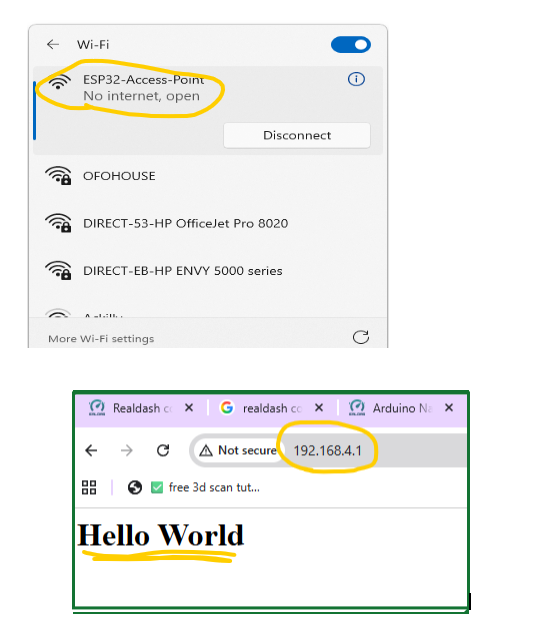
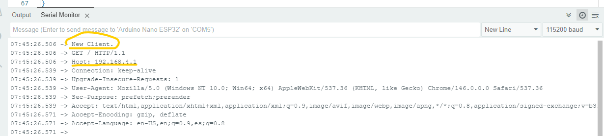
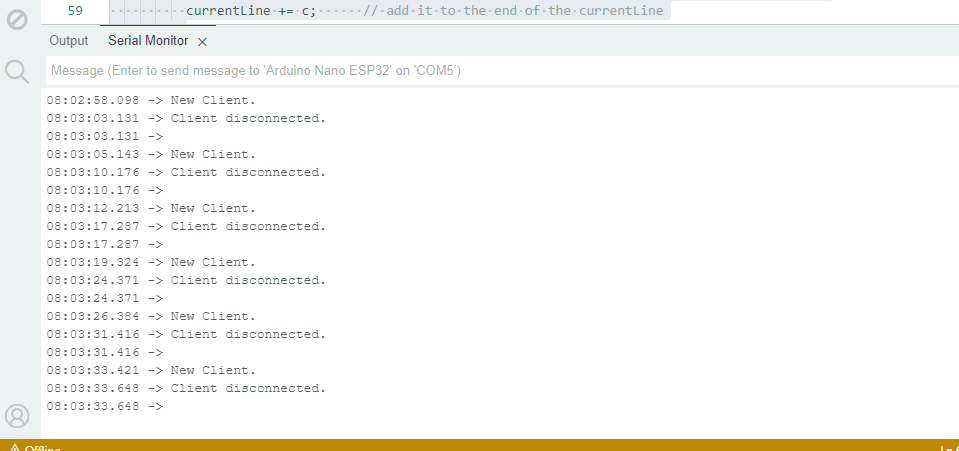
Alright, I tried this new code based on the RealDash CAN arduino Example, massage it a little bit to fit my application…basically I replaced Serial.write for server.write use the example XML file
still can’t connect. Below the Arduino sketch

#include <WiFi.h> // WiFi Library

const char* ssid = “300ZX-ESP”; // Network Name
WiFiServer server(80); // Set web server port number to 80, make sure RD matches

// Arduino digital and analog pins
unsigned int digitalPins = 0;
int analogPins[7] = {0};

unsigned int rpm = 0;
unsigned int kpa = 992; // 99.2
unsigned int tps = 965; // 96.5
unsigned int clt = 80; // 80 - 100
unsigned int textCounter = 0;

void setup()
{

Serial.begin(115200); // This baud rate most likely will change when connected to RealDash
WiFi.mode(WIFI_AP); // Set WiFi to Access Point mode

WiFi.softAP(ssid, NULL); // Start the softAP without a password (second argument is NULL)
//delay(1500);
while (!Serial){} // Wait for the Serial Port to be available, then continue with the set up

Serial.print(“AP Created with SSID: " + String(ssid));
Serial.println(” NO PASSWORD REQUIRED");
Serial.print("IP Address: ");
Serial.println(WiFi.softAPIP()); // Typically 192.168.4.1

}

void loop()
{
server.begin();
Dummy_Values(); // Call Subroutine to simulate some values
ReadDigitalStatuses(); // Call Subroutine to read digital values pins 1-13
ReadAnalogStatuses(); // Call Subroutine to read analog values pins A0-A7
SendCANFramesToWiFi(); // Call Subroutine to send CAN data via WiFi
}

//Subroutines

void Dummy_Values()
{
// just some dummy values for simulated engine parameters
if (rpm++ > 10000)
{
rpm = 500;
}
if (kpa++ > 2500)
{
kpa = 10;
}
if (tps++ > 1000)
{
tps = 0;
}
if (clt++ > 230)
{
// all values in frame are handled as unsigned values. To have negative values,
// offset actual value and write corresponding conversion to xml file imported to RealDash
clt = 0;
}
if (textCounter++ > 4000)
{
textCounter = 0;
}

delay(5);

}

void ReadDigitalStatuses()
{
// read status of digital pins (1-13)
digitalPins = 0;

int bitposition = 0;
for (int i=1; i<14; i++)
{
if (digitalRead(i) == HIGH) digitalPins |= (1 << bitposition);
bitposition++;
}
}

void ReadAnalogStatuses()
{
// read analog pins (0-7)
for (int i=0; i<7; i++)
{
analogPins[i] = analogRead(i);
}
}

void SendCANFramesToWiFi()
{
byte buf[8];

// build & send CAN frames to RealDash.
// a CAN frame payload is always 8 bytes containing data in a manner
// described by the RealDash custom channel description XML file
// all multibyte values are handled as little endian by default.
// endianess of the values can be specified in XML file if it is required to use big endian values

// build 1st CAN frame, RPM, MAP, CLT, TPS (just example data)
memcpy(buf, &rpm, 2);
memcpy(buf + 2, &kpa, 2);
memcpy(buf + 4, &clt, 2);
memcpy(buf + 6, &tps, 2);

// write first CAN frame to serial
SendCANFrameToWiFi(3200, buf);

// build 2nd CAN frame, Arduino digital pins and 2 analog values
memcpy(buf, &digitalPins, 2);
memcpy(buf + 2, &analogPins[0], 2);
memcpy(buf + 4, &analogPins[1], 2);
memcpy(buf + 6, &analogPins[2], 2);

// write 2nd CAN frame to serial
SendCANFrameToWiFi(3201, buf);

// build 3rd CAN frame, rest of Arduino analog values
memcpy(buf, &analogPins[3], 2);
memcpy(buf + 2, &analogPins[4], 2);
memcpy(buf + 4, &analogPins[5], 2);
memcpy(buf + 6, &analogPins[6], 2);

// write 3rd CAN frame to serial
SendCANFrameToWiFi(3202, buf);

// build 4th frame, this is a text extension frame
// only send once at 1000 loops
if (textCounter == 0)
{
SendTextExtensionFrameToWiFi(3203, “Hello RealDash, this is Arduino sending some text data”);
}
else if (textCounter == 1000)
{
SendTextExtensionFrameToWiFi(3203, “Tomorrow’s forecast: Lots of sun and 30 degrees centigate”);
}
else if (textCounter == 2000)
{
SendTextExtensionFrameToWiFi(3203, “Now Playing: Insert your favorite song info here”);
}
else if (textCounter == 3000)
{
SendTextExtensionFrameToWiFi(3203, “Message from Arduino: All systems running at nominal efficiency”);
}
}

void SendCANFrameToWiFi(unsigned long canFrameId, const byte* frameData)
{
// the 4 byte identifier at the beginning of each CAN frame
// this is required for RealDash to ‘catch-up’ on ongoing stream of CAN frames
const byte serialBlockTag[4] = { 0x44, 0x33, 0x22, 0x11 };
server.write(serialBlockTag, 4);

// the CAN frame id number (as 32bit little endian value)
server.write((const byte*)&canFrameId, 4);

// CAN frame payload
server.write(frameData, 8);
}

void SendTextExtensionFrameToWiFi(unsigned long canFrameId, const char* text)
{
if (text)
{
// the 4 byte identifier at the beginning of each CAN frame
// this is required for RealDash to ‘catch-up’ on ongoing stream of CAN frames
const byte textExtensionBlockTag[4] = { 0x55, 0x33, 0x22, 0x11 };
server.write(textExtensionBlockTag, 4);

// the CAN frame id number (as 32bit little endian value)
server.write((const byte*)&canFrameId, 4);

// text payload
server.write(text, strlen(text) + 1);

}
}