Dash Design for Beginners - ARC Gauge

For this guide, we are doing all asset edits via Photoshop or a similar photo editing software.

There are multiple ways to go about designing assets for a dash. There really isn’t one correct way to do so. I’m simply going over in detail the way I do so.

For an Arc Gauge the assets you can use are:

  • Background Image
  • Arc Image
  • Segment Image
  • Mid Segment Image
  • Mask Image

I’ve personally never used Mask for an Arc Gauge. For complete customization through the app, you would need to create both a Segment and Mid Segment asset.

Obviously an Arc Image is needed show the changes in the value we are monitoring. Everything else, I combine it into one Background Image which is NOT adjustable through the app. I do this so I may set warning areas to be a different color and add some effects to my text.

ARC IMAGE

It represents the value you are monitoring. Common useages are:

  • RPM
  • Speed
  • Fuel Level
  • Coolant Temperature
  • Throttle Position

KEEP this asset white. This will allow you to adjust the color in RealDash.

First, set the values for Normal, Warning, and Critical for your Arc Gauge:
Edit → Select Gauge → Input & Values

To adjust color for them:
Edit → Select Gauge ->Look’n Feel → Colors → Arc Blend Color

At the bottom left:
Editing Level → Normal, Warning or Critical

This will assign the value range and the color you want for each level.

If you do an edit while Editing Level is ALL, this will delete the colors assigned.

BACKGROUND IMAGE

As you can see I have everything already designed and set to a specific size that I personally like.

ARC GAUGE

Here is a final look at the [Arc Gauge]. The ARC asset is layered ontop of the BACKGROUND asset through the app. If you set colors for each level the whole ARC asset will change depending on the current value of what input you are montoring.

1 Like

UNDERSTANDING ANGLES AND SIZE

The arc gauge goes in a clock-wise direction. You set the Start Angle and the Sweep Angle in RealDash to match how you assets:

Look’N Feel → Special → Angles and Offsets

My personal favorite for RPM or Speed is:

  • Start Angle = 240
  • Sweep Angle = 240

The black shoes the 240 start angle. The red shows the end of the 240 sweep angle.

240 sweep angle is easily divisable. For RPM if it goes up to 8000, then every 1000 is 30 degrees. For speed, with a Max Speed of 160, every 10 mph is 20 degrees. With a Max Speed of 200, every 10 mph is 12 degrees.

I hope you get the gist. It’s just basic math.

DISPLAY DIMENSIONS

The dimensions of your display are very important. You can desig an Arc Gauge to be small enough to fit inside the boudnary or make an Arc Gauge thats bigger. Arc Gauges are very flexible in sizing and design. You can get very creative with the angles you use.

For these examples 1024 x 600 is the size of the display.

The RED represents the screen dimensions.
The WHITE represents the Arc Gauge dimensions.

EXAMPLE 1

Maybe you want a giant RPM to fill up the whole screen. The assets dimensions would be 1024x1024. Your Start Angle would be 270. Your sweep Angle would be 180.

You’d only need to design the upper half as it’ll be the only part used/visible on the screen.

EXAMPLE 2

Maybe you want two Arc Gauges side by side, one for RPM and one for speed. Since the width of the screen is 1024, you divide in half to get 512. Here the gauge assets would be 512x512. Start and Sweep Angel as you please.

For these examples the assets have a dimension of 500x500 for the canvas.
We are also making an RPM Gauge.
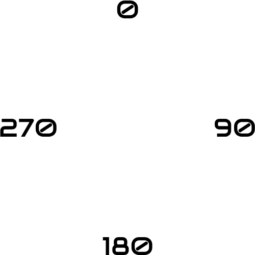
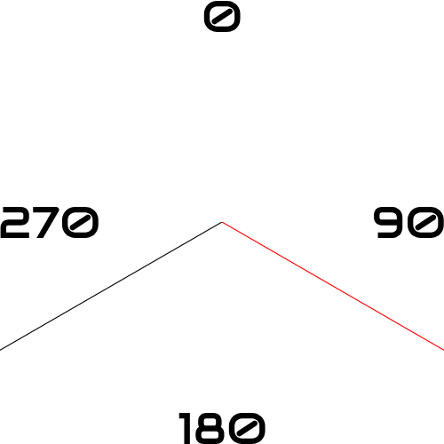
The RPM Gauge is using a Start Angle of 240 with a Sweep Angle of 240.

CREATING A BACKGROUND

When creating a background you can have different layers, ex:

  • Borders
  • Segments
  • Mid Segments
  • Text

OUTER BORDER

You can have a border anywhere. On the outside of the gauge, on the inside, or maybe both.

Here we’ll be making an outer border.

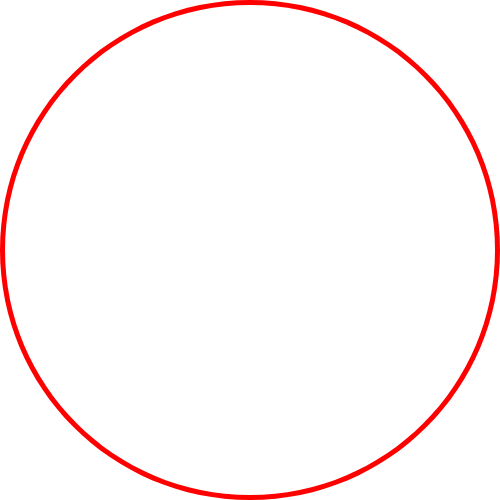
First I’ll insert a red circle with the same dimensions as the canvas, 500x500.
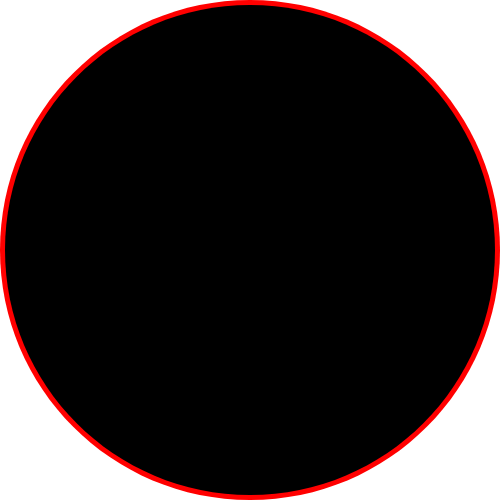
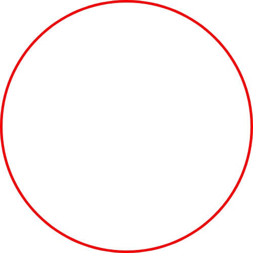
Then you add circle ontop thats black with a smaller dimensions.
The smaller the inner circle the thicker the border.
We’ll do 490x490 for the dimensions of the inner circle.

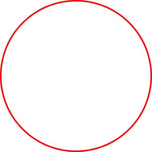
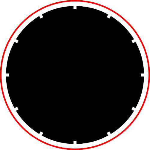
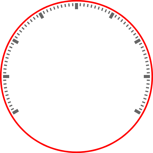
This shows how it would look layered on top. If you want to keep the black circle like that, thats fine. What I usually do is “select the pixels” of the black circle and “delete the selection” on the red circle. This leaves me with a transparent background as shown below.

Leaving it transparent will let you see the background of display, whether you want to keep it a solid black, put an image, etc.

SEGMENTS

I have my Segments be wider and taller then my Mid Segments.
This allows them to pop out and be easily seen.

The Segments will be rectangles that are 10x480 centered on the canvas.

It’s smaller then my black circle to leave a bit of a gab between it and the border.
You don’t need the gap if you don’t want to.
If you don’t, i usally make the height slightly taller then the black circle.

Here, the height would be 492 since the black circle’s height was 490.
This helps it blend into the circle.
I’ve notice sometimes there’s a small gap if they are the same size.

We then make a duplicate of the segment and rotate it 30 degrees.
We repear this procees until we cover the full 360.

Copy/Paste plus knowing how angles works makes this easy to do.

Once done I usually merge all copies of the segment layers.
It’s easier to adjust them as one.

MID SEGMENTS

The Mid Segments we will use rectangles that are 4x480 centered on the canvas.
We want them on the thinner side as there are more of them.

We will have our Segments 30 degrees apart.
If you want 9 Mid Segments between 2 Segments, you’d need to rotate each Mid Segment 3 degrees.
Rotate your original Mid Segment 3 degrees.
Here duplicate and rotate 3 degrees 8 more times.

Merge all those Mid Segment layers together.
Here duplicate and rotate 30 degrees 6 more times.

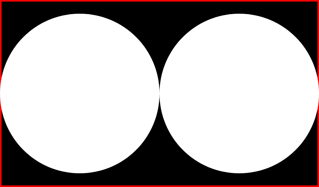
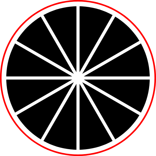
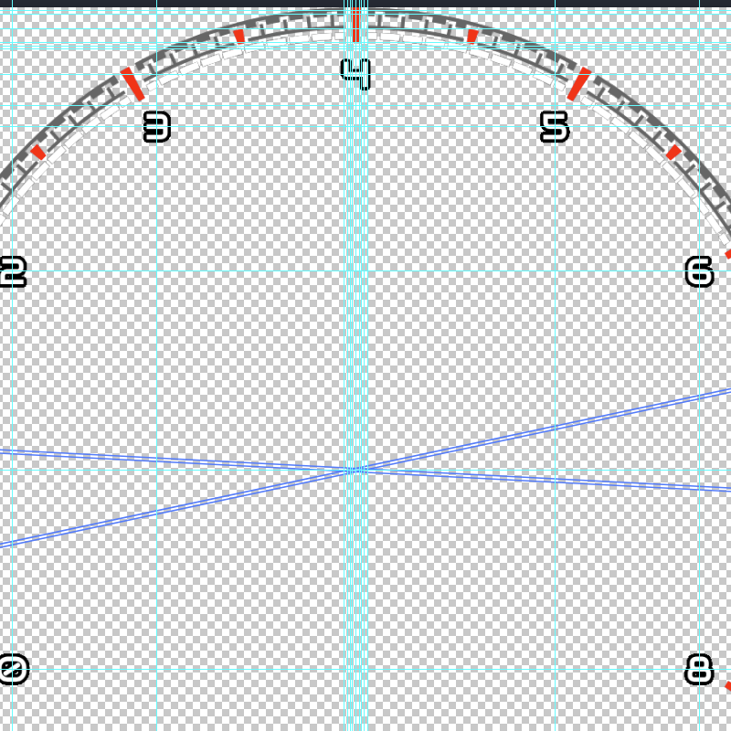
Here is how it will look with both Segments and Mid Segments togther.

ADUSTING SEGMENT AND MID SEGMENT LENGTH

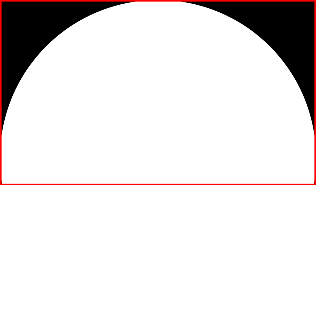
Here we’ll add another one or two circles on top again to adjust the lengths of our Segments and Mid Segments. You’ll only need one circle if you want them the same length or two circles for different lengths. Here we’ll use two.

My Mid Segments height is 480 and I want them to have a height of 10. So 480 - 2(10) = 460 for the size of my first circle. The 2 is for 10 on each side.

Add your circle. Have it behind your Segments and infront of your Mid Segments.

Now the Segments I want to have double the height, so 20. So 480 - 2(20) = 440. My second circle measuring 440 over my segments.

Add your circle. Have it infront of your Segments.

Done!

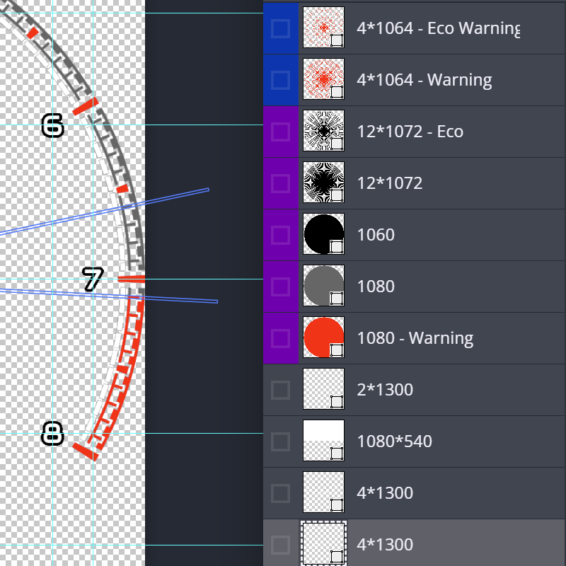
If you want a solid black background you can just leave it. I opt for deleting them. You select the area of the circles and delete the selected area on the segments and midsegments.

Also again, I opt to delete the part’s not used.

You could also selectively delete. Keep the border but delete only the excess segments.

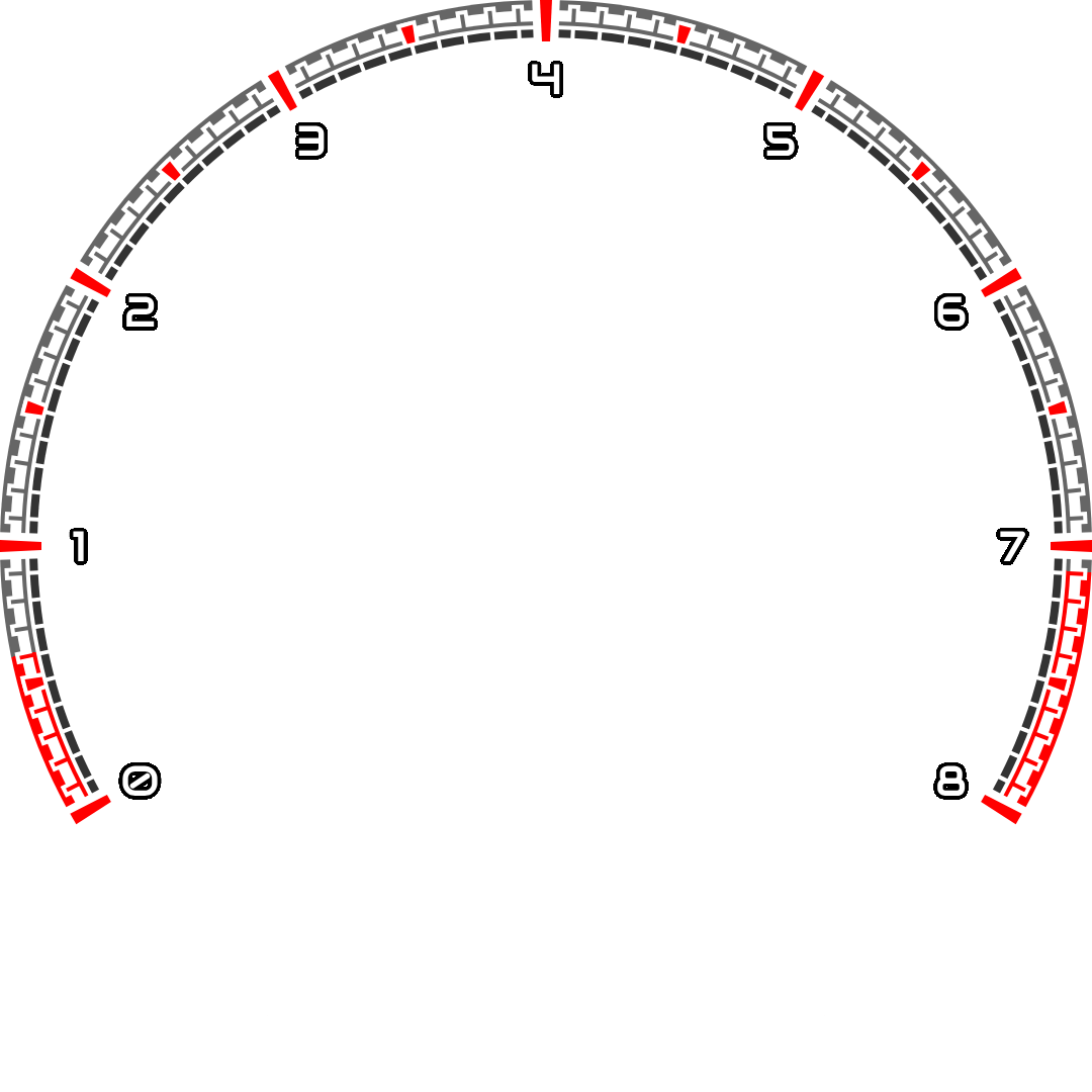
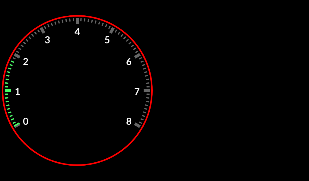
Now we will repeat the process for the markers but we’ll make them greyed out. Why? This arc gauge will use the segments we created as the arc gauge fill.

So you can save your first asset as such for your arc image.

So once you repeat the process for the segments but in a grey, you’ll have this for your background image.

2 Likes

While creating this i realized how difficult it maybe to add the numbers in photoshop for some. It take a lot more time tryna find the right distance and adding alot of guides.

So for simplicity.

Double Check that:

Look’N Feel → Special-> Angles & Offsets
Start Angle: 240
Sweep Angle: 240

Look’N Feel → Special-> Auto Scaling
Size Scale:100
Text Size: [Set to what you desire]
Text Offset: [Set to how far you want it from the center of the image]
Max digits: 1 [This is how many digits you see so RPM can look like 1 or 1000. The 1000 is 4 digits.]
Segments: [you count 0 as a segment. An RPM with 8k would have 9 segments then, 0 + every 1k]

End results should look like this.

That’s the gauge we created for RPM.

2 Likes

You can make so many variations here. You can make the border shaded, have a design LIke mine does. My border, the very first image, you can see i integrated the mid segments to the lower part of the border.

Then I had 2 type of segments. My main one for every 1000 rpm and then every other 500 rpm. Aside from being different size I made a different color and they didn’t have a perfect box shape as i skewed the inner ends.

I measured out and manually put in numbers and by doing so I added a black border to them so when I add a glow in the back they would be seen easily still.

You could also see I changed colors for my border which is a lighter grey and the background of the actual arc gauge which is darker. That and I made custom warning zones that are red.

but if you can make a similar basic gauge like I did then you already grasped the conecpt at least.

From there you just have to experiment and ask questions as everything is a lot more in detail of how to do.


Here are just examples of how my edit files can look and how many guides I have. This one had a few more guides as I scewed the end of my segments and ontop of that I wante the sides of the segments to be transparent.

Hope you find this useful. Please let me know.

2 Likes

Thank you so much, this is very helpful, after I am done and figuring out the rest I will share the result, thanks again.

1 Like

Thank you for these tutorials. Pinned the thread.

I’ll try to add on to this as I have time and depending on what’s asked.

I’ll be trying to post more tutorials while also making the current ones alot cleaner and informative.