Hey everyone,
I’d like to make a small digital speedo for my Harley 883 in order to replace the current speedo.
While I’m not still entirely sure on what kind of hw/dispaly I will use (at the moment I’m using an old smartphone for testing), I’m focused on understanding how to write the XML to read the ODB2 data from the ECU.
I’m also pretty sure it’s doable because I have an external ECU (Vance & Hines FP3) that has an app that shows dashboards and data, but from a graphic point of view it sucks and I’d like to have a cool/custom interface.
I’ve got pretty good information on the internet so far:
But I have none to little programming understanding, so I’d like to have some guidance from you.
I’m not asking you to do it, but just a direction.
I’ve read the realdash_obd2.xml example file, but I don’t know where to start.
If you could give some real example, that would be fantastic.
Thanks for the reply Jani!
Actually I haven’t tested it yet as I’m still waiting the cable for connecting the ELM327 into the bike.
But according to this guy http://momex.cat/en/HD-tacho-part4 Harleys have J1850 VPW canbus and it should use SAE J2178-4.
The J1850 stream contains the following commands (found by trial and error, no official Harley Davidson documentation was used):
28 1b 10 02 xx xx : rpm, xxxx = rotations/minute * 4
48 29 10 02 xx xx : speed, xxxx = km/h * 128
48 3b 40 xx : gear in neutral if (xx & 0x20), clutch engaged if (xx & 0x80)
48 da 40 39 xx : turn signals, xx = 1,2,3 for left/right/both
68 88 10 03 : check engine indicator off
68 88 10 83 : check engine indicator on
a8 3b 10 03 xx : current gear, xx = 1,3,7,15,31,63 for gears 1-6
a8 49 10 10 xx : engine temperature, xx = degrees Fahrenheit
a8 69 10 06 xx xx : odometer, xxxx = ticks, each tick = 0.4 meters
a8 69 10 86 xx xx : same as above, but a wraparound occured
a8 83 10 0a xx xx : fuel consumption, xxxx = ticks, each tick = 0.000040 liters
a8 83 10 8a xx xx : same as above, but a wraparound occured
a8 83 61 12 dx : fuel gauge, x = level (0-15)
Are these data/info enough for editing the XML file and make it specific for the bike? If they are, could you please explain me how to use it?
When you get your OBD2 adapter, experiment in OBD2 monitor to see what kind of a data you get. Once you get a good idea and confirmation of how the data protocol works, we can take a look of how to make a XML for it.
I took a quick look at the HarleyDroid source code, and it seems like its using ATMA command to monitor all traffic, essentially working as a CAN adapter. I recommend that you purchase a OBDLink MX adapter and use it as a CAN adapter with RealDash to monitor the entire CAN bus. As soon as you find the CAN ids and data for them, its quite easy to make a XML from them.
Greetings to everyone who reads this text.
Сontinue to dig into the topic.
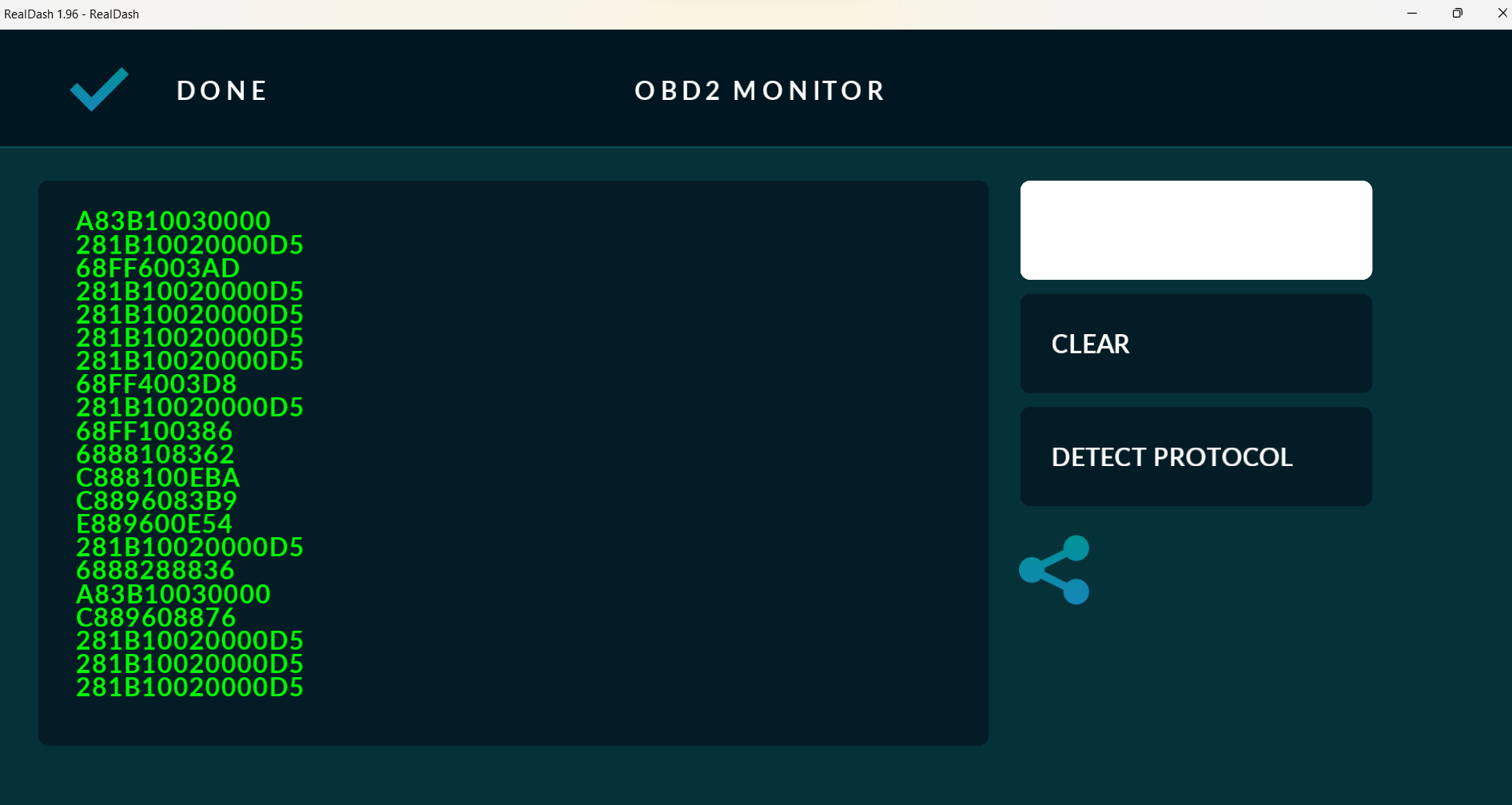
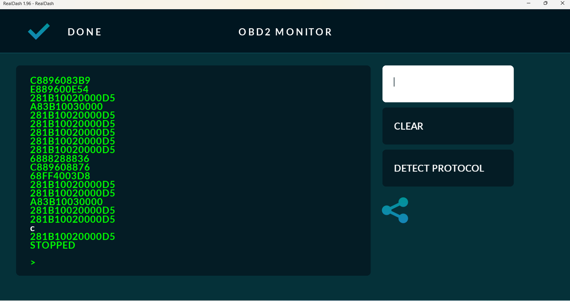
I was able to get a data stream from the J1850 bus using the ATMA command.
For example, a frame with information about engine speed looks like this 28 1B 10 02 00 00 D5
Rotation speed data is represented by bytes 5 and 6.
Using ATMR1B I can receive this frame from the data bus.
I continue to study the specification for ELM327 and the XML protocol description file for REALDASH and experiments with a motorcycle data bus.
I need motivation to continue digging=)
Using the ATMA command and the correct XML file, is it possible to transfer data to Realdash?
What do I (besides knowledge =)) lack, how to make friends with Harley and realdash?
Are commands from the init section sent to the adapter once when the realdash is connected to the adapter while configuring the hardware?
Are commands from the rotation section executed with a certain frequency after executing commands from init?
I apologize for the stupid questions.
The data I receive from the motorcycle contains information about the coolant temperature looks like that
A8 49 10 10 3E 50
The Fahrenheit value of ECT is in the fifth byte.
How to retransmit this to targetid = “14” of realdash input?
The command from the rotation section looks like this
Thanks for help.
Addition.
According to the instructions for elm327 and my experiences with the adapter OBDLink LX, any command sent after entering ATMA should interrupt the execution of ATMA.
You really cannot use ATMA with OBD2 connection type. ATMA (Monitor All) starts streaming all data in the bus, so it works differently than typical OBD2; Poll value → Receive Value type communication.
You should try the CAN connection instead. Create a CAN connection as OBDLink CAN adapter type, see CAN monitor for your data and create a CAN XML instead.
Yes. Then you can see if data is received in CAN Monitor of the connection settings and start developing the CAN XML that will describe the frames for RealDash.
And to clarify, OBD2 XML and CAN XML are completely different files and are not compatible with each other.
I performed several experiments.
OBDLink LX is connected to the RD as a CAN adapter and from the Mitsubishi Pajero and Volvo xc70 I was able to receive a data stream in the RD monitor.
When experimenting with a motorcycle, I was unable to achieve data flow from the data bus.
RD connect to adapter → then in the RD monitor I see Timeout → the indicators tell me that the device is not connected → reconnecting → then the connection drops again. And further in a circle.
Exactly the same behavior when the adapter is connected to a power source only.
All available speeds and protocols have been tried in CAN monitor menu.
At first I thought about the ELM327 input filters, then I realized that they are not used in MA mode.
In CAN mode does RD send ATMA to OBD adapter?
In this mode, is ATSP sent to the adapter?
It’s clear. Thank you. in the terminal I manage to listen to the j1850vpw bus when I use atsp0 or atsp2. In any other case there is silence in the terminal. It’s still not clear to me why the adapter breaks the Bluetooth connection when I try to listen to the j1850vpw in the can mode of the adapter. any ideas on this?
I understand it. However, in MA mode I can listen to the bus in the terminal, and see all the messages on it as if it were CAN.
So there is no way to transfer data from the j1850 to the RD CAN monitor?
Maybe a custom RD build for non-standard cases?