I am trying to connect a simple temperature analog signal through a GaugeArt Analog to Digital converter to CAN protocol, and I have tried looking through the forums with no luck. Im not sure this is the forum I should post this question.
As I understand I need to be able to program for the specific address, byte, and scale from volts to units
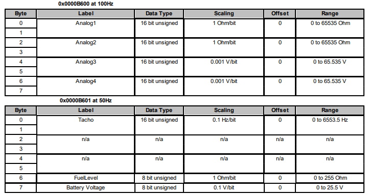
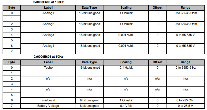
URL if Image doesnt appear: http://downloads.emecloud.com/GaugeArt_Analog_to_Digital_converter_CAN_ID_Chart.png
I can see the GaugeArt device is sending messages over the CAN bus, but I am unable to figure out how to map them to a gauge. The image below is the CAN message being sent. I am trying to configure the Analog signals table 1 to a gauge for Temperature. Below the chart I have included the CAN messages I can see. Any help would be most appreciative.
can0 0000B600 [8] 0B BD FF FF 13 5D 13 5E
can0 0000B600 [8] 0B BD FF FF 13 5D 13 5C
can0 0000B601 [8] 00 00 00 00 FF 7F 00 00
can0 0000B600 [8] 0B C3 FF FF 13 5D 13 5E
can0 0000B600 [8] 0B C3 FF FF 13 5B 13 5C
can0 0000B602 [8] 13 63 03 00 00 00 00 0A
can0 0000B601 [8] 00 00 00 00 FF 7F 00 00
can0 0000B600 [8] 0B C0 FF FF 13 5E 13 5E
can0 0000B600 [8] 0B BB FF FF 13 5B 13 5C
can0 0000B601 [8] 00 00 00 00 FF 7F 00 00
can0 0000B600 [8] 0B BE FF FF 13 5B 13 5C
can0 0000B600 [8] 0B C0 FF FF 13 5B 13 5C
can0 0000B601 [8] 00 00 00 00 FF 7F 00 00
can0 0000B600 [8] 0B C0 FF FF 13 5B 13 5B
can0 0000B600 [8] 0B BB FF FF 13 5B 13 5C
can0 0000B601 [8] 00 00 00 00 FF 7F 00 00
can0 0000B600 [8] 0B BD FF FF 13 5B 13 5B
can0 0000B600 [8] 0B BD FF FF 13 5D 13 5C
can0 0000B601 [8] 00 00 00 00 FF 7F 00 00
can0 0000B600 [8] 0B C3 FF FF 13 5B 13 5C
can0 0000B600 [8] 0B C3 FF FF 13 5D 13 5E
can0 0000B602 [8] 13 63 03 00 00 00 00 0A
can0 0000B601 [8] 00 00 00 00 FF 7F 00 00
can0 0000B600 [8] 0B C3 FF FF 13 5D 13 5C
can0 0000B600 [8] 0B C0 FF FF 13 5B 13 5C
can0 0000B601 [8] 00 00 00 00 FF 7F 00 00
can0 0000B600 [8] 0B C3 FF FF 13 5D 13 5E
can0 0000B600 [8] 0B C3 FF FF 13 5B 13 5B
can0 0000B601 [8] 00 00 00 00 FF 7F 00 00
can0 0000B600 [8] 0B C0 FF FF 13 5D 13 5E
can0 0000B600 [8] 0B BD FF FF 13 5B 13 5C
can0 0000B601 [8] 00 00 00 00 FF 7F 00 00
can0 0000B600 [8] 0B BD FF FF 13 5D 13 5E
can0 0000B600 [8] 0B C0 FF FF 13 5B 13 5C
can0 0000B601 [8] 00 00 00 00 FF 7F 00 00
can0 0000B600 [8] 0B C0 FF FF 13 5B 13 5C
can0 0000B600 [8] 0B C0 FF FF 13 5B 13 5C
can0 0000B602 [8] 13 63 03 00 00 00 00 0A