Hi All,
Sorry if this has already been covered and for the newb questions:
What do you all think of as an ideal set up to run Realdash as a cars dash display and possibly touch screen control for lights etc.
I am building a car with VW Beetle based, no OBD2. Building the wiring harness for the whole car from scratch so open to any suggestions.
I am using a Core 4 speeduino ecu for all engine data
I was thinking along the lines of a Vim3 running Android for Realdash
Is it possible to link to an Arduino to capture signals from other analogue and digital circuits of the car ie hall sensors or drive train for speed, and lighting circuits for headlight on off dip and full beam reporting?
Can I pull data from the arduino and the ecu at the same time via USB’s or serial?
My ideal solution would be to run Realdash and tuner studio on the same 12.3 touch screen lcd, which I believe may only be possible if using windows o/s as both apps can function on this platform, however this would mean steering away from the vim3 in favour of a different abc as far as I can tell.
You can connect speeduino over Bluetooth or direct usb, and arduino with realdash can protocol with usb, also if you use esp32 you can connect with bluetooth or wifi.
Arduino can read analog and digital signals to send this to realdash, and you can send data from realdash to arduino.
I prefer to run on Android and just run realdash, you have the same info from tuner studio and you not tuning ECU all the time, but this is just my preference.
Here some examples of arduino (teensy 3.2) sending and receiving info in realdash (installed on 1976 beetle):
Thanks Hugo,
Great info.
What are the CAN modules in your steering wheel videos? Little black boxes!
PS That’s a great set up you’ve put together there, any info you can share is appreciated.
Cheers
Matt
They are like PMU (power management units) for control loads like head lamps, horn, windshield wiper motor, etc and also have some digital and analog inputs to send info to my system, like hood, trunk, doors, outside temp sensor, gear shift sensor, etc.
Instead of wiring all the car, I have 3 modules with can bus communication the front module for head lamps, horn, windshield washer motor, and windshield wiper motor ( this is bmw motor controller by lin bus) and hood status , outside temp sensor inputs, middle module to power radio, aim dash, main power for ECU, injectors, door status inputs and rear module for rear ligths, trunk status and gear shift sensors.
Sorry for late response I don’t know why don’t have any notifications
For can bus I use teensy 3.2 with SN65HVD230 transceiver most can bus messages are defined by me except for the VW messages for communication with the VW radio
Sorry for late response I don’t know why don’t have any notifications
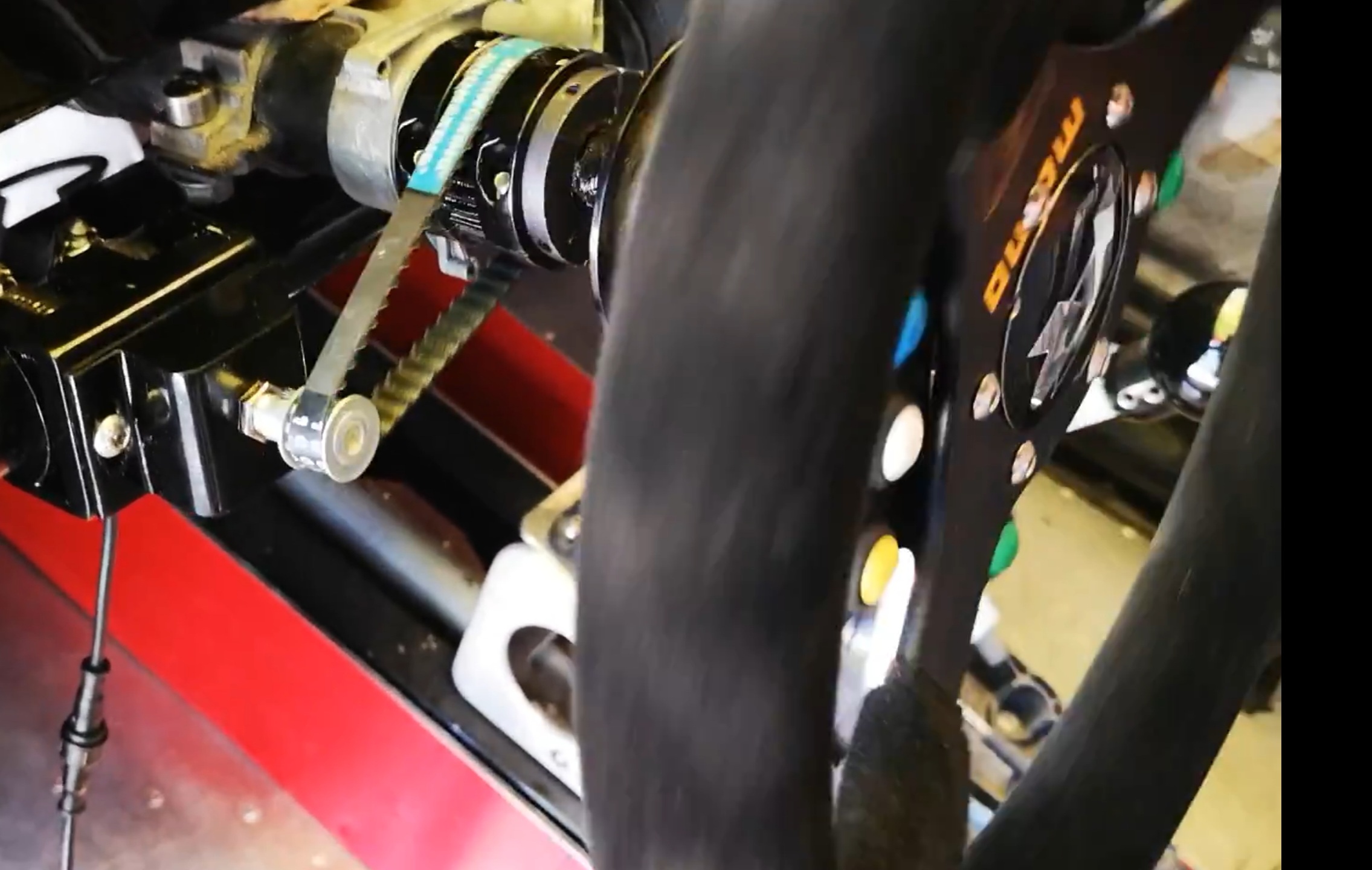
I map potentiometer value to the values radio need over can bus. It’s a 10 turn potentiometer with 3d printed support and 3d printer gear on steering shaft
Oh it’s the radio that does the actual drawing of the guide lines? I’ll need to see if I can figure out how to do some of that with my android radio if I can figure that out.
Yes the radio have the steering line guides, in my case the unit is for VW Jetta, Golf, Polo, Gol. Also have support for radar but in my case I don’t use this function.
I know most of the android radios are essentially all the same on the software side with settings in a hidden menu that turns on/off the different features. I would assume the radio has a canbus decoder box in the wiring in the back? Also the canbus messages you wrote to use the pot is mapped to the VW canbus message structure?
Sorry for late response, yes I emulate VW canbus messages I send messages for: power, ligths, outside temperature, winshield fluid level, rpm, speed, steering angle, doors, trunk, hood, seat bealt bucket, vol up/down and mute.
I check some messages from this pages: MKV GTI CAN-BUS data - Google Drive VW-CAN - OpenStreetMap Wiki
That’s an idea that I could emulate the VW protocols with my controller. I do think that the stock SW sensor on my MR2 doesn’t detect angles, but probably more like a hall sensor.
I attach the program, but it’s not intended to be for public so it’s very messy and specific for my custom setup, but basically I read the pot value and average the value.
  total = total - readings[readIndex];
  readings[readIndex] = analogRead(Steering);
  total = total + readings[readIndex];
  readIndex = readIndex + 1;
  if (readIndex >= numReadings) {
    readIndex = 0;
  }
  Steering_average = total / numReadings;
Then just map the values of pot (you need to change this depending on your sensor value) to the values the radio need (this is a VW radio if yours it’s diferent you need to mach this values to your car): in my case the guide lines need values from 1 to 73 for the right turn and -56 to -128 for the left turn.
And finally I send the message over can bus. The VW steering angle message for infotaiment ID 963 (0x3C3) bite 0,1 the others values in the messages are not for the radio, arefor my AIM dash and other modules.