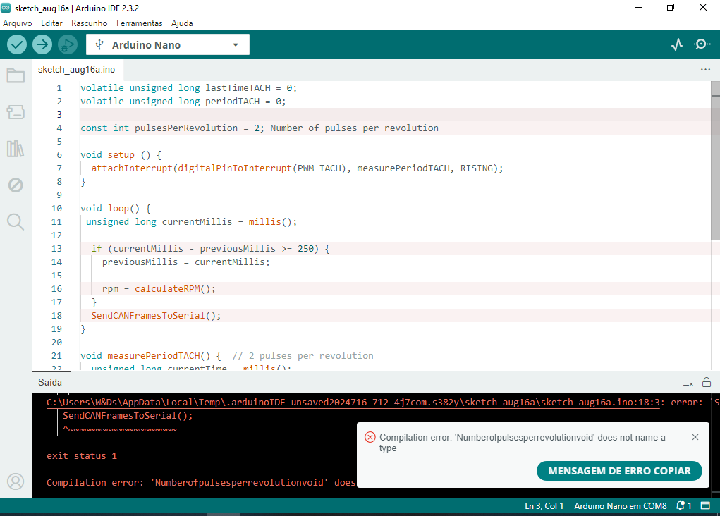
I’m having trouble viewing how the RealDash screen works. RPM includes some tachometer lines in the ino code, but it doesn’t make the tachometer work on the RealDash screen. The sensor even reads the pulses when you pass your hand in front of it and also sends them to the Arduino, but nothing happens on the RealDash screen. It only changes from state 1 to 0 when the sensor reads them. The modified code is below:
Arduino Nano 328P controller
/**
- ============================================================================
- Name : RealDash_CAN.ino
- Part of : RealDash
- Author : Jani Immonen
- Created : 15.10.2017
- Arduino example sketch of how to use RealDash CAN protocol.
- This example code is free for any use.
- www.realdash.net
- ============================================================================
**/
// Arduino digital and analog pins
#include <TimerOne.h> //biblioteca TimerOne
#define sensor 8 //define o pino 8 para o sinal do sensor
unsigned int digitalPins = 0;
int analogPins[7] = {0};
unsigned long voltas,periodo;
unsigned long rpm;
bool L_sensor = 0; //variável para a leitura atual do sensor
bool LA_sensor = 0; //variável para a leitura anterior do sensor
//unsigned int rpm = 0;
unsigned int kpa = 992; // 99.2
unsigned int tps = 965; // 96.5
unsigned int clt = 80; // 80 - 100
unsigned int textCounter = 0;
void setup()
{
Timer1.initialize(1000); //obs.: 1000000 é igual a 1 segundo. E, 1000 é igual a 1 milissegundo
Timer1.attachInterrupt(Timer); //TimerOne é anexado ao “void Timer ()”
pinMode(sensor, INPUT); //configura o pino do sensor como entrada
Serial.begin(115200); //inicializa serial
delay(100);
}
void loop()
{
//faz a leitura do sensor e atribui esse valor para a variável L_sensor
L_sensor = digitalRead(sensor);
//SE L_sensor e LA_sensor estiver igual a 1, faça…
//obs.: superfície preta, sensor = 1 (led do sensor apaga) – superfície branca, sensor = 0 (led do sensor acende)
if (L_sensor == 1 && LA_sensor == 1){
LA_sensor = 0; //retorna a variável LA_sensor para zero
voltas++; //soma uma unidade na variável voltas
rpm = 1/(periodo/60000.0); //calcula o RPM em função do período decorrido
periodo = 0; //retorna pra zero a variável periodo
}
//SE L_sensor e LA_sensor estiver igual a zero, faça…
if (L_sensor == 0 && LA_sensor == 0)
LA_sensor = 1; //retorna a variável LA_sensor para 1
delay(10); //delay para não travar o arduino
ReadDigitalStatuses();
ReadAnalogStatuses();
SendCANFramesToSerial();
// just some dummy values for simulated engine parameters
if (rpm++ > 10000)
{
rpm = 500;
}
if (kpa++ > 2500)
{
kpa = 10;
}
if (tps++ > 1000)
{
tps = 0;
}
if (clt++ > 230)
{
// all values in frame are handled as unsigned values. To have negative values,
// offset actual value and write corresponding conversion to xml file imported to RealDash
clt = 0;
}
if (textCounter++ > 4000)
{
textCounter = 0;
}
delay(5);
}
void ReadDigitalStatuses()
{
// read status of digital pins (1-13)
digitalPins = 0;
int bitposition = 0;
for (int i=1; i<14; i++)
{
if (digitalRead(i) == HIGH) digitalPins |= (1 << bitposition);
bitposition++;
}
}
void ReadAnalogStatuses()
{
// read analog pins (0-7)
for (int i=0; i<7; i++)
{
analogPins[i] = analogRead(i);
}
}
void SendCANFramesToSerial()
{
byte buf[8];
// build & send CAN frames to RealDash.
// a CAN frame payload is always 8 bytes containing data in a manner
// described by the RealDash custom channel description XML file
// all multibyte values are handled as little endian by default.
// endianess of the values can be specified in XML file if it is required to use big endian values
// build 1st CAN frame, RPM, MAP, CLT, TPS (just example data)
memcpy(buf, &rpm, 2);
memcpy(buf + 2, &kpa, 2);
memcpy(buf + 4, &clt, 2);
memcpy(buf + 6, &tps, 2);
// write first CAN frame to serial
SendCANFrameToSerial(3200, buf);
// build 2nd CAN frame, Arduino digital pins and 2 analog values
memcpy(buf, &digitalPins, 2);
memcpy(buf + 2, &analogPins[0], 2);
memcpy(buf + 4, &analogPins[1], 2);
memcpy(buf + 6, &analogPins[2], 2);
// write 2nd CAN frame to serial
SendCANFrameToSerial(3201, buf);
// build 3rd CAN frame, rest of Arduino analog values
memcpy(buf, &analogPins[3], 2);
memcpy(buf + 2, &analogPins[4], 2);
memcpy(buf + 4, &analogPins[5], 2);
memcpy(buf + 6, &analogPins[6], 2);
// write 3rd CAN frame to serial
SendCANFrameToSerial(3202, buf);
// build 4th frame, this is a text extension frame
// only send once at 1000 loops
if (textCounter == 0)
{
SendTextExtensionFrameToSerial(3203, “Hello RealDash, this is Arduino sending some text data”);
}
else if (textCounter == 1000)
{
SendTextExtensionFrameToSerial(3203, “Tomorrow’s forecast: Lots of sun and 30 degrees centigate”);
}
else if (textCounter == 2000)
{
SendTextExtensionFrameToSerial(3203, “Now Playing: Insert your favorite song info here”);
}
else if (textCounter == 3000)
{
SendTextExtensionFrameToSerial(3203, “Message from Arduino: All systems running at nominal efficiency”);
}
}
void SendCANFrameToSerial(unsigned long canFrameId, const byte* frameData)
{
// the 4 byte identifier at the beginning of each CAN frame
// this is required for RealDash to ‘catch-up’ on ongoing stream of CAN frames
const byte serialBlockTag[4] = { 0x44, 0x33, 0x22, 0x11 };
Serial.write(serialBlockTag, 4);
// the CAN frame id number (as 32bit little endian value)
Serial.write((const byte*)&canFrameId, 4);
// CAN frame payload
Serial.write(frameData, 8);
}
void SendTextExtensionFrameToSerial(unsigned long canFrameId, const char* text)
{
if (text)
{
// the 4 byte identifier at the beginning of each CAN frame
// this is required for RealDash to ‘catch-up’ on ongoing stream of CAN frames
const byte textExtensionBlockTag[4] = { 0x55, 0x33, 0x22, 0x11 };
Serial.write(textExtensionBlockTag, 4);
// the CAN frame id number (as 32bit little endian value)
Serial.write((const byte*)&canFrameId, 4);

// text payload
Serial.write(text, strlen(text) + 1);
}
}
void Timer(){
periodo++; //soma 1 ao valor atual do período
}