Hi Everyone,
I’m trying to figure out if there is an option to Send CAN frame that can be recognized by my EMU Black as Switch.
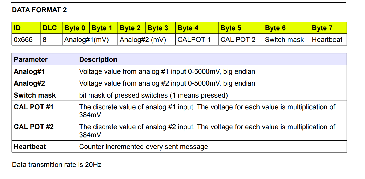
I’m looking into Switch to CAN official ecumaster module and this is the info.
So my question is…how should potentially look such CAN frame in Realdash
Sure, you can send CAN frame 0x666 from RealDash to ECU to emulate the switch board. I could be something like this:
<frame id="0x666" writeInterval="1000">
  <value name="ECUMASTER: Analog #1" offset="0" length="2"></value>
  <value name="ECUMASTER: Analog #2" offset="2" length="2"></value>
  <value name="ECUMASTER: CALPOT 1" offset="4" length="1"></value>
  <value name="ECUMASTER: CALPOT 2" offset="5" length="1"></value>
  <value name="ECUMASTER: Switch 1" offset="6" length="1" units="bit"></value>
  <value name="ECUMASTER: Switch 2" offset="6" length="1" units="bit" conversion="V>>1"></value>
  <value name="ECUMASTER: Switch 3" offset="6" length="1" units="bit" conversion="V>>2"></value>
  <value name="ECUMASTER: Switch 4" offset="6" length="1" units="bit" conversion="V>>3"></value>
  <value name="ECUMASTER: Switch 5" offset="6" length="1" units="bit" conversion="V>>4"></value>
  <value name="ECUMASTER: Switch 6" offset="6" length="1" units="bit" conversion="V>>5"></value>
  <value name="ECUMASTER: Switch 7" offset="6" length="1" units="bit" conversion="V>>6"></value>
  <value name="ECUMASTER: Switch 8" offset="6" length="1" units="bit" conversion="V>>7"></value>
  <value name="ECUMASTER: Heartbeat" offset="7" length="1"></value>
</frame>
This will create a CAN frame with given value names which is sent to CAN bus once a second AND every time any of the specified values change with RealDash actions.
1 Like
In the past couple of days i had the opportunity to test the CAN function. Initially i had a few issues but i finally was able to send CAN frame to enable the switch.
Thank you very much !
Link to my GitHub repo if needed:
GitHub - damtrx/Real-Dash-CAN-Stream-XML-for-EMU-Black
2 Likes
Do you mind if we put your Ecumaster XML to RealDash as a build-in option?
Go ahead. To be honest the code was yours 
I just adapted the XML file, so it can be used in the context of the Emu Black with CAN adapter.
I will continue with my small project, so i will update only my GitHub page.
There are few things that needs to be done
- Extract the RD file from the android storage and put it in the GitHub page, so people can use it as an example. Should be able to do it during the weekend
- Fix the check engine light bits (didn’t have enough time to spend on this one.)
Oh and BTW you guys are awesome ! I’ve been working in the IT industry for years, but never had such support before in my life for any other product.
Thanks again. Really appreciated your help .
1 Like
Ok, i had a few spare hours to test the switches and analog inputs
Analog inputs are fine for now but i have a problem with the switches
So, in the manual it says that Byte 6 contains the information for all the switches. It uses Switch mask
This should look like this 0000 0000 to disable all the switches and 1111 1111 to enable all of them
So if i want to enable just a single one like Switch 1 i should send a frame like 0000 0001
For switch two i should flip just the second bit like 000 0010
For both i should uses 0000 0011 and so on for the others
What i did to test the switches
- Create a button
- Create an action for switch 2
- For action i’m using ‘set a value’ and assign as input SW2
- Set value to 4 ( trying to enable second bit)
This will enable SW2 but it will disable SW1 because it will send 0000 0010
My question now is how i should flip just a single bit without messing with the others?
Declare each value in XML as a ‘units="bit’ and set the value to with action to 0 or 1. RealDash will then build a CAN frame to send without interfering with other bits on the data.
Thanks for the reply.
I tried with this approach but still when i write 1 as action it still changes the other bits.
    <value name="EMU Black: Switch 1" offset="6" length="1" units="bit" startbit="0" bitCount="1"></value>
    <value name="EMU Black: Switch 2" offset="6" length="1" units="bit" startbit="1" bitCount="1"></value>
    <value name="EMU Black: Switch 3" offset="6" length="1" units="bit" startbit="2" bitCount="1"></value>
    <value name="EMU Black: Switch 4" offset="6" length="1" units="bit" startbit="3" bitCount="1"></value>
Should work just fine. Just out of curiosity, try defining frame this way:
    <value name="EMU Black: Switch 1" offset="6" length="1" units="bit"></value>
    <value name="EMU Black: Switch 2" offset="6" length="1" units="bit" conversion="V>>1"></value>
    <value name="EMU Black: Switch 3" offset="6" length="1" units="bit" conversion="V>>2"></value>
    <value name="EMU Black: Switch 4" offset="6" length="1" units="bit" conversion="V>>3"></value>
That is the format that we typically use when writing digital statuses back to the CAN bus.
Ok i think i have partial success. It looks like that part of the CAN frame is shifted. Switch 1 is not working , switch 8 can’t be enabled. All other switches are working as expected.
Now the funny part is that BIT 7 which should be Switch 8 is actually Switch 7
    <value name="EMU Black: Switch 1" offset="6" length="1" units="bit" startbit="0" bitCount="1"></value>
    <value name="EMU Black: Switch 2" offset="6" length="1" units="bit" startbit="1" bitCount="1"></value>
    <value name="EMU Black: Switch 3" offset="6" length="1" units="bit" startbit="2" bitCount="1"></value>
    <value name="EMU Black: Switch 4" offset="6" length="1" units="bit" startbit="3" bitCount="1"></value>
    <!--<value name="EMU Black: Switch 4" offset="6" length="1" units="bit" startbit="4" bitCount="1"></value>-->
    <value name="EMU Black: Switch 5" offset="6" length="1" units="bit" startbit="5" bitCount="1"></value>
    <value name="EMU Black: Switch 6" offset="6" length="1" units="bit" startbit="6" bitCount="1"></value>
    <value name="EMU Black: Switch 7" offset="6" length="1" units="bit" startbit="7" bitCount="1"></value>
That is because startbit counts from 0, so startbit 0-7 are bits 1 to 8.
I’m sorry but i think you got me wrong
Bit 0 is … well it is doing all sort of weird things
Bit 1 is Switch 2 which is correct
Bit 2 is Switch 3 which is correct
Bit 3 is Switch 4 is correct
Bit 4 is…nothing
Bit 5 is Switch 5
Bit 6 is Switch 6
Bit 7 is Switch 7 which is not correct
So the problem is why bit 4 is nothing and bit 0 is actually changing everything
According to the manual Byte 6 (8 bits) should address all the switches - 8
Each bit is corresponding to switch number
So it is kind of shifted with a bit on the left/right but just after bit 4
Any ideas ?
Don get me wring, 6 out of 8 is a huge success
Alright, there is clearly something that I do not understand from your setup, sorry