Please note that Link G4X does not send the serial data and therefore does not work with these instructions. G4X can be connected using a CAN connection.
Also, Apple does not allow normal USB devices to connect to their devices, so USB connection option is not available on iOS.
Link ECU software configuration:
Using the PCLink G4+ tuning software, connect a PC to the ECU using the normal USB tuning cable.
Navigate to ECU settings>Configuration>Configuration. Here we need to set the Datastream mode and the baud rate. The suggested Data stream mode is “Continuous - 12Hz” and the suggested baud rate is 38400.
realdash_link_configuration.png
After making this change you need to perform a Store (Ctrl+S), then power cycle the ecu (power off then back on).
Hardware Connection:
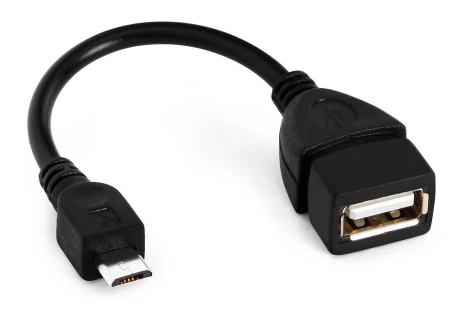
The ECU needs to be connected to the tablet/smartphone using your normal USB tuning cable. At the ECU end this cable should be plugged in to the same port that you would normally use for tuning the ECU. The other end of the cable can plug in to any spare USB port on the tablet/phone, if yours only has a micro USB port then you will need a “Micro USB OTG adapter”. A flexible cable type adapter like shown below is suggested to prevent damage to the port from force/stress.
RealDash Configuration:
Attach the USB cable to your vehicle and device. On Android, use appropriate USB-OTG adapter.
Open RealDash, on first start select language, and then go to ‘Garage’
Tap vehicle door and then the instrument cluster. Tap ‘Add’ on connection list
I running Link G4x Plug in evo 3 on android head unit with realdash(With ET.dash / Motec skin). I alrdy calibrated everything,but just having 1 problem (the vehicle speed shown 0).
I calibrated on Ecu Digital input to DI 8 Speed sensor (On Ecu everything run correctly,i have check on ecu that speed sensor is active,Misc Vehicle speed is running normal on log)
I had tried to calibrate the realdash input to ECU Speed Sensor,selected the data input to Ecu Vehicle Speed / VSS 1 ,and calibrated the Gauge math to V*103. But turn out still the same (the vehicle speed is not run on realdash)
beside this problem,all function runs fine (only for the Vehicle Speed) Any way can help me to calibrate the vehicle speed?
Was there any value on Debug Data View that corresponds to your vehicle speed? If not, you do need to modify the CAN connection XML to send the speed data over CAN bus.
On your Link PC software you con configure what data is sent over the CAN. You need to configure the ECU to output the custom speed value, and then add that new value into RealDash CAN XML file so RealDash understands where the speed value is coming from.
There could be some other way to configure the ECU to send the standard speed value over CAN, but unfortunately I’m not an expert on configuring Link ECU.
Hello everyone,
Regarding the hardware, I have a Raspberry Pi 4 with 4GB RAM, running Raspberry Pi OS 64-bit.
I use a 12V to 5V power converter, passive cooling, and RealDash is installed.
My idea was to build a virtual instrument cluster for my car (Audi A4 B6, 2002, 1.9 TDI 74kW, engine code AVB) with basically all functions. In other words, I would remove the original cluster, keep only its electronics, and place a new 3D-printed frame in its place.
However, I was convinced the car had CAN bus communication. In the meantime, I found out that it actually uses the ISO 9141 protocol (K-Line). ChatGPT told me that it’s possible to communicate with all modules in real time using a KKL 409.1 cable.
What I would like to know is if anyone has already done something similar, and if there are PID files available for a similar car model. ChatGPT also mentioned that it’s possible to program all of this in Python.
If anyone has experience with a similar project, I would greatly appreciate any information.
Hey team so I have followed this forum to an absolute Tee and for some reason when i go to check the CAN monitoring theres absolutely nothing there. So im using a Z32 Link G4+ with a link CAN cable to a bluetooth OBD2 connector. Now ive checked in my Hyundai Iload if the Bluetooth OBD2 connector works in reeldash and it does but it wont work for my Link G4+ Ill upload some photos below for reference. I can send more screen shots of how I tried to set it up and I have tried practically every combination on Realdash app but still to no avail! Ive been at this for days and I really need to get it working please help!
Hey mate do you have an email address I can show you some pictures of what ive done and see if you can figure out where im going wrong as lowing the speed didnt work either.