I could get most of numeric datas but I couldn’t get text based values.
One example from Syvecs abbreviation is “calSwitch”
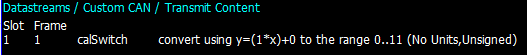
calSwitch basically a rotary switch that shows which ecu calibration map selected as text values CAL01, CAL02, CAL03,12
Adaptronic ecu has very good XML file. I’ve looked up some examples from it.
I added a text gauge, select input - calSwitch
which didn’t worked. It shows zero. When I turn the rotary switch it goes zero to one.
I couldn’t understand how actually it works. Can you help ?
in my S6, one line item would be sufficient. the calswitch information would be set to one particular frame / slot.
the return value is 0, 1, 2, 3, etc.
so the gauge name would be CalSwitch, and would get a value back that tells you which Cal your on. Mine doesn’t return text? Also the value is unsigned. Or you could make the name = “Cal”, or “Calibration” and your custom gauge then shows the calibration number.
Currently the only way to show this number as text is to use trigger when value changes and action to set gauge text. Make a trigger that fires when calSwitch value changes to 0 and link that to action that sets gauge text to ‘CAL0’. Then make another trigger that fires when calSwitch value changes to 1 to set the text to ‘CAL1’, and so on.
Thanks.
So as far as I understood Syvecs is not streaming text values?
This code works on me as well.
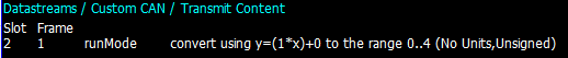
I tried the same code for “SyncDiag” abbreviation (which shows sync faults) and it turns numeric as well.
There is also “limpMode” abbreviation that shows the faults but all turns with numeric.
So is it currently impossible to get text messages?
Yeah so the data being sent in those examples is a numeric value. 0,1,2 etc. Those values correspond to a gear, limp mode, calibration etc.
From the post made by realdashdev, it appears you can use those numeric values to trigger displaying custom text on the real dash side. I’m not familiar with that process so cant help from experience sorry.
Thanks. I think I understand what to do now. Just considering about latency. I’m using a cheap seed analyser right now.
There are many items that needs to be considered/fired. Would this cause CPU resources down? I’m running onboard cpu miniitx intel board.
cheers
btw, You are very talented and this software is amazing. It is not just dash software. It includes many softwares inside(canbus monitor, gauge editing tools etc.) I paid the application in windows store and android platforms. Is this working in Chrome OS? I may install chrome os if i can sort xml
Hi
I decided not to create a new topic, I will write here.
Please tell me, how to map one of the same bits in the same frame with different values to several functions?
For example: id - 089; 2 bit in the frame - “0B”-turn signal to the left
id - 089; 2 bit in the frame - “33”-turn signal to the right
As you do not specify which bits in the byte are the “2 bit in the frame”, the best guess would be bit 4 for left turn and bit 5 for right turn. In that case values would be defined in XML file:
Thanks!
I was wrong. I meant the second byte in the frame - 00 00 “0B” C0 42 02 00
I do not know which bit in the byte is responsible for the function, I will find out and write later.
Hi!
I figured out the bits responsible for the functionality. As a result:
-left turn signal- 00 00 “30” 00 00 00 00
in binary, the second byte is - “00110000”
-right turn signal- 00 00 “08 80” 00 00 00
in binary, the second and third bytes is - “00001000-10000000”
Please tell me how an XML file should look like?
In the functions of turn signals, two bits are used, not one.
To the left - two bits in the third byte - “00110000”
To the right - one bit in the third and one in the fourth byte - “00001000-10000000”
Hi!
I’m trying to adjust the speed readings, but nothing works. The speed is calculated from 4 and 5 bytes:
4.xx speed
5.xx speed
Speed calculation: (4.xx * 255 + 5.xx)/100
No, I know that the first byte is B0, the second is B1, etc.
For some reason, the conversion function except “V” does not work.
For example:
- does not work, the result is “2”. Under B4 does not see the data and adds 2 to 0, result is 2.
But conversion=“V+2” in the same line works correctly!
Thank you for explaining the work of the “offset” function, I did not understand how it works, I did not find its description. Now everything is clear, and everything works as it should!
Thank you very much!